This page outlines the functional description of the iPower-DC2 to confirm operability and safety functions.
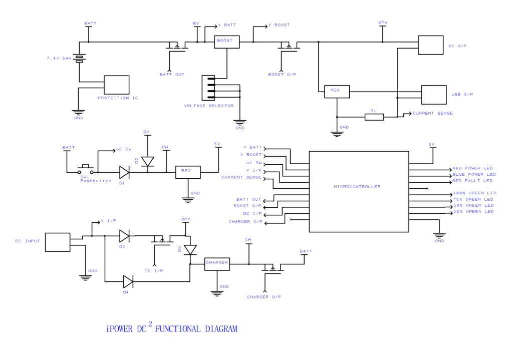
In the following descriptions, component references and any implied pin outs refer to the functional diagram not the actual circuit for the DC2. The switches where referred are MOSFET switches apart from SW1. Circuit references are in this format. This functional diagram is to show the functional parts of the DC2 only, is simplified and does not represent the actual schematic accurately.
Connecting Power at DC input
When DC power is applied, the charger is enabled via D4. This presents a voltage ‘CH‘, which applies power to the 5V regulator. The microcontroller starts up and measures the input voltage ‘V I/P‘, switches on the CHARGER O/P switch and BATT OUT switch. This starts the BOOST circuit and V BOOST is measured. If V BOOST is not similar to V I/P (e.g. the selector switch does not match) then the unit enters FAULT mode. The appropriate LED power indicator is illuminated (RED for 24V, BLUE for 12V and both for 9V). If the V BOOST and V I/P are similar then DC I/P is switched on which provides power to OPV. The DC jacks and the USB now have power.
The charger is active. The protection IC sits between the Lithium battery pack and ground and will disconnect if excessive charge/discharge or temperatures are encountered. The battery voltage is monitored via V BATT and the appropriate LED(s) are activated dependent on battery status.
If V BOOST changes during operation (e.g. selector switch moved) then the unit will FAULT.
Power output is monitored via a resistive shunt in the ground return – CURRENT SENSE. If in excess of unit ratings the Microcontroller will initiate FAULT and switch off DC I/P, CHARGER O/P and BOOST O/P.
The unit cannot be switched off when DC input power is connected.
Battery Operation
The DC input fails and this is detected via DC I/P. The microcontroller then ensures continuing power by activating the BOOST O/P switch whilst simultaneously switching off DC I/P and CHARGER O/P. Since BOOST is already powered, OPV is now at V BOOST. OPV provides power via D5 to the charger to maintain the CH input and hence keep the 5V regulator powered. The battery voltage is monitored via V BATT and the appropriate LED(s) are activated. See note on Lithium Battery Discharge below.
If the battery is at End Of Discharge (EOD) then the Microcontroller will switch off all switches, notably BATT OUT which disconnects power from the 5V regulator thereby switching the Microcontroller and hence the DC2 OFF.
In battery mode the unit can be switched off. The Microcontroller senses the ON/OFF (SW1) switch is pressed via uC SW. If pressed for 3 seconds the Microcontroller will switch OFF BATT OUT, DC I/P and CHARGER O/P and holds itself in a reset mode for 2 seconds. If SW1 is not released during these 2 seconds the unit will attempt to cold start – see below.
Upon return of DC input power DC I/P and CHARGER O/P are switched ON and BOOST O/P is switched OFF and the unit behaves as described in “Connecting Power” above.
Cold Starting
With the unit powered down with no DC output there is no active circuit monitoring SW1 and therefore practically zero drain on the Lithium battery. When the SW1 is pressed, this connects the battery voltage to the 5V regulator which will start up the Microcontroller.
The unit will then behave as in Battery Operation above.
Lithium Battery Discharge
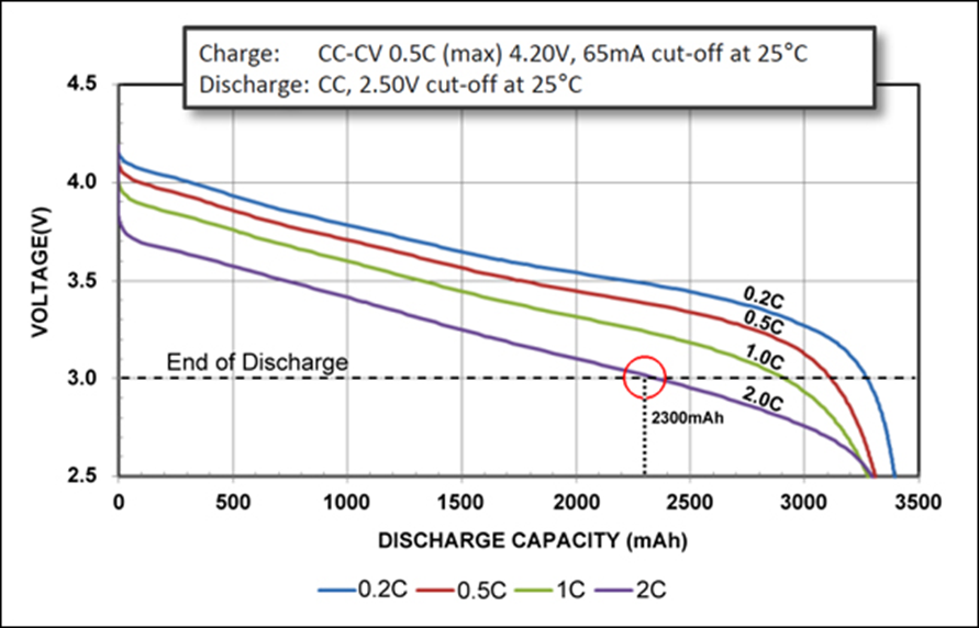
The above is a typical discharge graph taken from the data for a Panasonic NCR18650B 3200mAh battery. It is not the battery used in the DC2 but just representative of the technology. The key take aways are:
- The more you take from the battery the less capacity you have. E.g., discharging at twice its capacity, 6400mA, the actual discharged capacity is 2300mAh. You need to discharge at 0.5C to get the stated capacity and you will get more for even lower discharge rate.
- The voltage across the battery isn’t reflective of its state of charge (SOC) when it’s discharging. It depends upon how much current is being drawn from it. This is why the battery indicator is approximate. For example, if discharging at 2C, then at half capacity (1600mAh), the voltage is 3.2V. At 1C it is 3.4V, 0.5C 3.55V and at 0.2C over 3.6V. So there’s no way to get an accurate measure of the SOC based on the battery voltage – unless it is unloaded. E.g. you can only tell this when the unit is not operating from its battery. Hence the charge level indicator is much more accurate as to the SOC.
- The battery voltage falls away more quickly in the first few moments.
Without complex algorithms that are beyond the scope of the Microcontroller in the DC2 it is not possible to have an accurate level meter when the DC2 is discharging – as the load varies to whatever load requirement the DC2 has. A battery indicator on a mobile phone may be quite accurate as the phone knows within a good margin what the constant discharge on the battery is. On the DC2 a customer may connect a low powered CCTV camera operating at ½W, or high powered routers and hubs operating at 25W. These will have very different discharge characteristics.
As a consequence, the battery level indicator is approximated and is calibrated so that the reduction from 25% to zero takes the longest time. For example it would appear misleading if the the unit fell from 100% to 50% charge in one hour, but then shut off 10 minutes later (e.g. going from 50% to 0%). Rather, it is calibrated so that if it took one hour to get from 100% to 50%, then you will have more than one hour of autonomy left. We consider this is a better indication.
The fall from 100% to 75% will occur relatively quickly – at high loads this may be within a few seconds or even immediately.